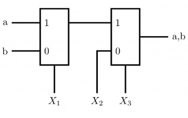
The following circuit implements a two-input AND gate using two 2-1…
2007
The following circuit implements a two-input AND gate using two 2-1 multiplexers. What are the values of X1, X2, X3 ?
- A.
X1=b, X2=0, X3=a
- B.
X1=b, X2=1, X3=b
- C.
X1=a, X2=b, X3=1
- D.
X1=a, X2=0, X3=b
Attempted by 65 students.
Show answer & explanation
Correct answer: A
Solution
Key idea: A 2-to-1 multiplexer with select S and data inputs D0 (selected when S=0) and D1 (selected when S=1) implements the logic
Out = (not S AND D0) OR (S AND D1).
Apply this to the shown circuit: the top multiplexer uses a as its select, with D0 given by X2 and D1 given by X1. Thus the output is
Out = (not a AND X2) OR (a AND X1).
Choose X1 = b (so D1 = b) and X2 = 0 (so D0 = 0).
Also set X3 = a (so the multiplexer select is a).
Substituting these into the multiplexer expression gives
Out = (not a AND 0) OR (a AND b) = 0 OR (a AND b) = a AND b.
Verification:
If a = 0, Out = 0 (since D0 = 0). This matches a AND b = 0.
If a = 1, Out = b (since D1 = b). This matches a AND b = b when a = 1.
Therefore the correct assignments are X1 = b, X2 = 0, X3 = a.
A video solution is available for this question — log in and enroll to watch it.