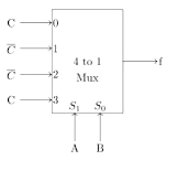
Consider the circuit in below figure. f implements
1996
Consider the circuit in below figure. f implements
- A.
(ABC)′+A′BC′+ABC
- B.
A+B+C
- C.
A⊕B⊕C
- D.
AB+BC+CA
Attempted by 64 students.
Show answer & explanation
Correct answer: C
To determine which boolean function the 4-to-1 Multiplexer (Mux) implements, we can derive its output equation based on the select lines and input lines.
Step-by-Step Derivation
A 4-to-1 multiplexer selects one of its four data inputs (I0, I1, I2, I3) based on the binary combination of its select lines (S1, S0).
From the given circuit diagram:
Select lines: S1 = A, S0 = B
Data inputs:
I0 = C
I1 = ~C
I2 = ~C
I3 = C
The general characteristic equation for a 4-to-1 Mux is:

Substituting our specific values into the equation:

Simplifying the Expression
Let's group the terms to recognize standard logic gates:
Grouping the first and last terms, and the middle two terms:

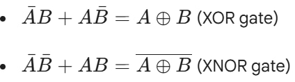
Recognize the standard XOR and XNOR relations:
Substitute these back into the expression:

Let Y = A ⊕ B. The expression becomes:
f = (~Y)C + Y(~C)
This is the exact definition of an XOR operation between $Y$ and $C$:
f = Y ⊕ C
Substitute Y = A ⊕ B back in:
f = A ⊕ B ⊕ C
A video solution is available for this question — log in and enroll to watch it.