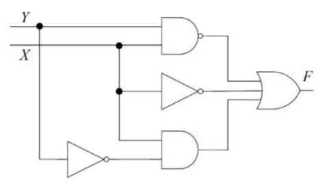
Consider the following logic circuit diagram. Which is/are the CORRECT…
2025

Consider the following logic circuit diagram.

Which is/are the CORRECT option(s) for the output function 𝐹?

  1. A.

    \(\overline{X Y}\)

  2. B.

    \(\overline{X}+\overline{Y}+X \overline{Y}\)

  3. C.

    \(\overline{XY}+\overline{X}+X \overline{Y}\)

  4. D.

    \(X+\overline{Y}\)

Attempted by 86 students.

Show answer & explanation

Correct answer: A, B, C

Key result: the output function F equals ¬(X·Y).

Step-by-step derivation:

  • Top gate: a NAND receiving X and Y, so its output is ¬(X·Y).

  • Middle inverter: inverts X, producing ¬X. This signal is one input to the final OR.

  • Bottom path: the inverter produces ¬X and the bottom AND receives X and ¬X, so that AND output is X·¬X = 0 (always false).

  • Final OR: combine the three inputs: ¬(X·Y) + ¬X + 0 = ¬(X·Y) + ¬X.

  • Use ¬(X·Y) = ¬X + ¬Y to see that ¬(X·Y) already includes ¬X, so the OR simplifies to ¬(X·Y).

Equivalence checks for the given algebraic expressions:

  • Expression ¬X + ¬Y + X·¬Y simplifies to ¬X + ¬Y (because ¬Y absorbs X·¬Y), which equals ¬(X·Y).

  • Expression ¬(X·Y) + ¬X + X·¬Y simplifies to ¬(X·Y) (because ¬(X·Y) = ¬X + ¬Y and that already covers the other terms).

  • Expression X + ¬Y is not equivalent; a counterexample is X=1, Y=1 where X+¬Y = 1 but ¬(X·Y) = 0.

Conclusion: the circuit implements F = ¬(X·Y). The two algebraic forms ¬X + ¬Y + X·¬Y and ¬(X·Y) + ¬X + X·¬Y are algebraically equivalent to ¬(X·Y), so they represent the same function; X + ¬Y does not.

A video solution is available for this question — log in and enroll to watch it.

Explore the full course: Gate Guidance By Sanchit Sir