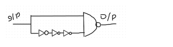
Consider the logic circuit with input signal shown in the
Consider the logic circuit with input signal shown in the figure. All gates in the figure shown have identical non-zero delay. The I/P signal which was at logic LOW is switched to logic HIGH and maintained at logic HIGH. The output
- A.
pulses from LOW to HIGH to LOW
- B.
stays LOW throughout
- C.
stays HIGH throughout
- D.
pulses from HIGH to LOW to HIGH
Attempted by 71 students.
Show answer & explanation
Correct answer: D
Initially, I/P=0, Output = 1, and the inputs of the NAND gates are 0, 1.
Since all the logic gates have "identical" non-zero delay "d", so, when I/P is switched to HIGH, after ‘3d’ time, the lower input of the NAND gate will have the correct value, But the upper input of the NAND gate will have correct value immediately. So, after ‘d’ time, output becomes 0, and after ‘4d’ time, output becomes High again.