The counter implemented by the following circuit diagram where inputs to the…
2017
The counter implemented by the following circuit diagram where inputs to the NAND gate are the outputs of the B and C flip-flops, is
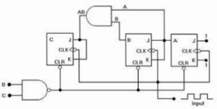
Answer: B. MOD-6 Counter — The correct option is B (MOD-6 Counter). The circuit represents a 3-bit ripple counter with an active-low clear (CLR) driven by a NAND gate. The inputs to the…
- A.
MOD-7 Counter
- B.
MOD-6 Counter
- C.
MOD-8 Counter
- D.
MOD-4 Counter
Attempted by 261 students.
Show answer & explanation
Correct answer: B
The correct option is B (MOD-6 Counter). The circuit represents a 3-bit ripple counter with an active-low clear (CLR) driven by a NAND gate. The inputs to the NAND gate are B and C. When C=1 and B=1 (state CBA = 1102, which is 6), the NAND gate outputs a 0, immediately resetting all flip-flops to 0002. Thus, the counter skips 6 and counts through 6 states: 0, 1, 2, 3, 4, 5.