The following figure best describes which kind of memory?
2017
The following figure best describes which kind of memory?
Answer: D. 64 x 4 ROM, Active Low Chip Select — Concept — A memory block diagram is read entirely from its pin signature, never from its outline. The count of address lines fixes how many locations can be…
- A.
64 x 16 RAM, Active High Chip Select
- B.
64 x 4 RAM, Active Low Chip Select
- C.
64 x 16 ROM, Active High Chip Select
- D.
64 x 4 ROM, Active Low Chip Select
Attempted by 21 students.
Show answer & explanation
Correct answer: D
Concept — A memory block diagram is read entirely from its pin signature, never from its outline. The count of address lines fixes how many locations can be selected: n address lines reach 2n distinct locations. The count of data lines fixes the word width, that is, how many bits sit at one location. The direction of the data lines, together with the presence or absence of a read/write control pin, fixes the class of memory: a read-only memory drives data outward only and needs no write path, while a read/write memory needs a bidirectional data bus and an explicit R/W input. Finally, a control input carrying an overbar, or drawn with an inversion bubble at the block edge, is asserted when it is driven LOW rather than HIGH.
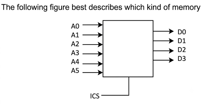
Applying it to the figure — Read the four pin groups of the block one at a time.
Six address lines A0 to A5 enter the block, so the number of addressable locations is 26 = 64.
Four data lines D0 to D3 leave the block, so each location holds a 4-bit word, giving a total capacity of 64 × 4 = 256 bits.
The data arrows point outward only, and no read/write or write-enable pin is present, so the stored contents can only be read out. That is the pin signature of a read-only memory (ROM); a read/write memory (RAM) would carry a bidirectional data bus plus a separate R/W input.
The single control input at the bottom is CS carrying an overbar, which the scan renders as the characters ICS. An overbarred control name means the pin is asserted when it is driven LOW, that is, an active-low chip select.
Cross-check — Set the three pin requirements of each candidate reading beside what the figure actually draws.
Reading | Data lines needed | Data path and control pins | Chip-select drawing |
|---|---|---|---|
64 x 16 RAM, Active High Chip Select | sixteen (D0-D15) | bidirectional bus plus an R/W pin | plain CS, no bar |
64 x 4 RAM, Active Low Chip Select | four (D0-D3) | bidirectional bus plus an R/W pin | CS carrying a bar |
64 x 16 ROM, Active High Chip Select | sixteen (D0-D15) | outward-only lines, no write pin | plain CS, no bar |
64 x 4 ROM, Active Low Chip Select | four (D0-D3) | outward-only lines, no write pin | CS carrying a bar |
The figure as drawn | four (D0-D3) | outward-only lines, no write pin | CS carrying a bar |
Result — Only one of the four readings agrees with the figure on all three counts, so the figure describes a 64 × 4 ROM with an active-low chip select.