In the latch circuit shown, the NAND gates have non-zero, but unequal…
GATE · 2017 · EC · Set 1 · Electronics and Communication Engineering
In the latch circuit shown, the NAND gates have non-zero, but unequal propagation delays. The present input condition is: P = Q = ‘0’. If the input condition is changed simultaneously to P = Q = ‘1’, the outputs X and Y are
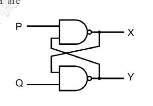
- A.
X = ‘1’, Y = ‘1’
- B.
either X = ‘1’, Y = ‘0’ or X = ‘0’, Y = ‘1’
- C.
either X = ‘1’, Y = ‘1’ or X = ‘0’, Y = ‘0’
- D.
X = ‘0’, Y = ‘0’
Attempted by 11 students.
Sign up free to check your answer
Sign up freeLoading lesson…