The circuit shown in the given figure is a
20072007
The circuit shown in the given figure is a
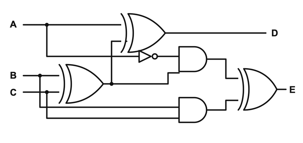
Answer: B. Full subtractor — Concept: A full adder and a full subtractor are both 3-input, 2-output combinational circuits (no clock or flip-flops). A full adder adds two bits plus a…
- A.
Full adder
- B.
Full subtractor
- C.
Shift register
- D.
Decade counter
Attempted by 563 students.
Show answer & explanation
Correct answer: B
Concept: A full adder and a full subtractor are both 3-input, 2-output combinational circuits (no clock or flip-flops). A full adder adds two bits plus a carry-in to produce a sum bit and a carry-out bit. A full subtractor subtracts one bit from another with a borrow-in to produce a difference bit (the XOR of all three inputs) and a borrow-out bit built from two AND terms that are mutually exclusive, combined by an OR gate — and since the terms never overlap, an XOR gate gives the identical result.
Application: Trace the given circuit gate by gate for inputs A, B, C and outputs D, E.
Step 1: The lower-left XOR gate takes B and C, giving B ⊕ C.
Step 2: The upper XOR gate takes A and this B ⊕ C signal, giving D = A ⊕ (B ⊕ C) = A ⊕ B ⊕ C.
Step 3: The A line also branches into a NOT gate, giving A′.
Step 4: The upper AND gate takes A′ and the same B ⊕ C signal, giving A′(B ⊕ C).
Step 5: The lower AND gate takes B and C directly, giving BC.
Step 6: The final gate on the right combines A′(B ⊕ C) and BC into E. It is drawn as an XOR gate rather than an OR gate — but A′(B ⊕ C) = 1 only when A = 0 and B ≠ C, while BC = 1 only when B = C, so the two terms can never be 1 together. Whenever two inputs can never both be 1, XOR and OR produce identical results, so E = A′(B ⊕ C) XOR BC = A′(B ⊕ C) + BC = A′B + A′C + BC.
Cross-check: A′B + A′C + BC is exactly the standard borrow-out expression of a full subtractor, and D = A ⊕ B ⊕ C is the standard difference expression. Testing A = 0, B = 0, C = 1 (0 − 0 − 1 needs a borrow, difference 1): B ⊕ C = 1, so D = 1, A′(B ⊕ C) = 1, BC = 0, giving E = 1 — matching the expected borrow of 1. The circuit also has no flip-flops or clock input anywhere, so it cannot be the shift register or decade counter options, which are sequential circuits.
Final answer: Full subtractor.
A video solution is available for this question — log in and enroll to watch it.