The below figure shows four $\text{D}$-type flip-flops connected as a shift…

GATE · 1987 · CS · Descriptive B

The below figure shows four $\text{D}$-type flip-flops connected as a shift register using a $\text{XOR}$ gate. The initial state and three subsequent states for three clock pulses are also given.
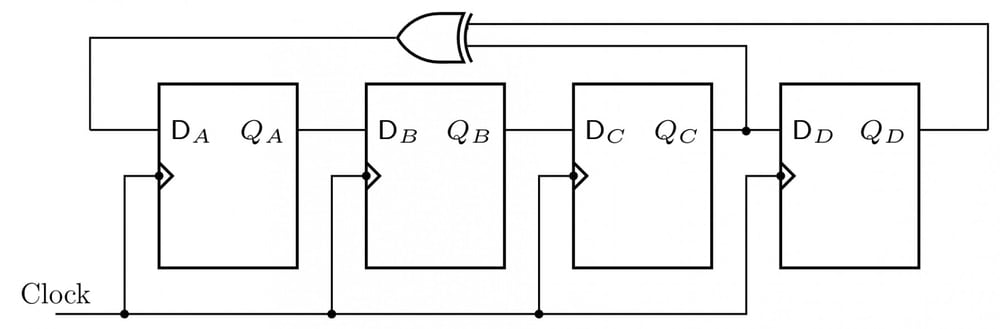
Four D flip-flops A, B, C, D share a clock. Outputs Q_A, Q_B and Q_C feed D_B, D_C and D_D respectively. Q_C and Q_D feed an XOR gate whose output feeds D_A.

StateQAQBQCQDInitial1111After the first clock0111After the second clock0011After the third clock0001\begin{array}{|l|c|c|c|c|}\hline\text{State}&Q_A&Q_B&Q_C&Q_D\\\hline\text{Initial}&1&1&1&1\\\text{After the first clock}&0&1&1&1\\\text{After the second clock}&0&0&1&1\\\text{After the third clock}&0&0&0&1\\\hline\end{array}

The state $Q_AQ_BQ_CQ_D$ after the fourth clock pulse is

  1. A.

    $0000$

  2. B.

    $1111$

  3. C.

    $1001$

  4. D.

    $1000$

Attempted by 5 students.

Sign up free to check your answer

Sign up free

Explore the full course: Gate Guidance By Sanchit Sir

Loading lesson…