

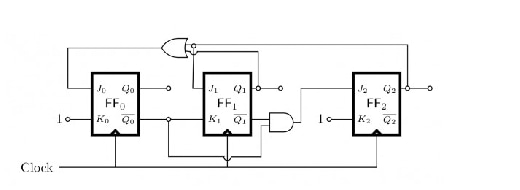
For the synchronous counter shown in Fig. 3, write the truth table of Q₀, Q₁,…
PYQ GATE 1990
For the synchronous counter shown in Fig. 3, write the truth table of Q₀, Q₁, and Q₂ after each pulse, starting from Q₀ = Q₁ = Q₂ = 0 and determine the counting sequence and also the modulus of the counter.
Sign up free to check your answer
Sign up freeLoading lesson…