

The below figure shows four \(\text{D}\)-type flip-flops connected as a shift…

PYQ GATE 1987

The below figure shows four D\text{D}-type flip-flops connected as a shift register using a XOR\text{XOR} gate. The initial state and three subsequent states for three clock pulses are also given.
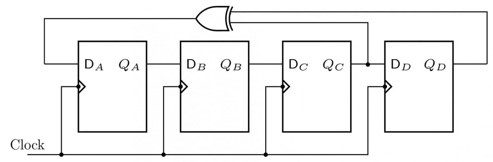
Four D flip-flops A, B, C, D share a clock. Outputs Q_A, Q_B and Q_C feed D_B, D_C and D_D respectively. Q_C and Q_D feed an XOR gate whose output feeds D_A.

StateQAQBQCQDInitial1111After the first clock0111After the second clock0011After the third clock0001\begin{array}{|l|c|c|c|c|}\hline\text{State}&Q_A&Q_B&Q_C&Q_D\\\hline\text{Initial}&1&1&1&1\\\text{After the first clock}&0&1&1&1\\\text{After the second clock}&0&0&1&1\\\text{After the third clock}&0&0&0&1\\\hline\end{array}

The state QAQBQCQDQ_AQ_BQ_CQ_D after the fourth clock pulse is

  1. A.

    00000000

  2. B.

    11111111

  3. C.

    10011001

  4. D.

    10001000

Attempted by 38 students.

Sign up free to check your answer

Sign up free

Explore the full course: Digital Electronics

Loading lesson…